Lighting control has become increasingly popular as we have started to be more conscious of our energy use. Early lighting control, beyond simple on/off, focused on dimming of light fixtures to reduce energy output when higher light levels weren't warranted. More intelligent systems that can control entire buildings at very precise levels are now available.
While lighting control systems require an additional capital cost and ongoing maintenance costs, these are usually dwarfed by energy cost savings over the life of a building.
Analog Lighting Control Systems
Analog lighting control systems use voltage to control the light output of a fixture. The most basic level of analog lighting control is the traditional on/off switch. The lights are "dumb" in that they have power-in and power-out, but do not have any communications components. When the switch is in the off position, there is no power running to the fixture. When the switch is flipped to the on-position, the light receives power and comes on.
Lights can be wired in series so that multiple fixtures are controlled by a single switch and three-way (or more) switches are available so that multiple switches can control a single group of light fixtures.
0-10V Dimming
0-10V (zero to ten volt) dimming is the standard analog lighting control system used in commercial and institutional buildings. It uses a direct current (DC) voltage signal to adjust light output. The signal varies from 1-volt to 10-volts, where the voltage corresponds to a specific light level. However, there are two different standards for how the dimming works: current sourcing and current sinking. It is important to understand the difference since the two standards are incompatible.
In current sourcing systems, the controller sends voltage to the light ballast or driver. When the controller sends 0-volts the light will be off and when the controller sends 10-volts the light would be set to maximum level.
In current sinking systems, the ballast or driver (the light fixture) sends 10-volts of current to the controller. The controller takes this 10-volts and, based on user input, uses a resistor to lower the voltage to the desired level. That lowered voltage, say 6-volts, is sent back to the light fixture, which receives the signal and dims the light down as appropriate.
A 0-10V control system is simpler than many digital systems, but that also means it has fewer features. Since it is a fairly basic system, fixture and component costs are generally lower; however, the 0-10V systems usually require more wiring, which increases installation costs. Finally, since there are limited programming inputs, costs for programming and commissioning are usually lower than on digital systems.
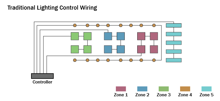
0-10V dimming is not addressable, meaning each fixture wired to the controller receives the same signal so all fixtures in the chain will dim to the same level together and each control zone requires a home run back to the controller. Unfortunately, if you want to rezone the system you need to rewire the fixtures and potentially add a home run back to the control panel. Finally, features are limited to on/off/dimming since the voltage signal only allows a single range of lighting levels.
The diagram below shows a wiring diagram for a traditional (non-addressable) lighting control system where each zone requires a home-run to the controller. Rewiring will be required if you want to change the zones.
Digital Lighting Control Systems
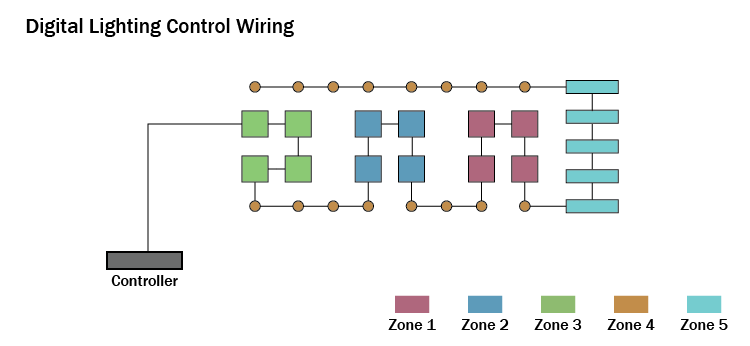
Modern digital lighting control systems provide many features above and beyond traditional 0-10V dimming systems. Digital systems send binary commands over a low-voltage wire in the form of combinations of 1s and 0s. This allows the system to send a virtually unlimited number of different commands so it isn't confined to simple dimming, but can also control other features such as color temperature so that buildings can have circadian lighting to mimic natural daylight cycles. In addition, the binary commands can contain information about what specific fixtures should be altered, which means each individual fixture can be addressable and zones can be changed with software rather than rewiring.
The diagram below shows the wiring diagram for an addressable digital lighting control system where fixtures can be daisy chained together without regard to zones. This allows zones to be changed in software rather than with rewiring.
Digital lighting control systems need to speak and understand the language of 1s and 0s that come through; this is referred to as a protocol. Digital lighting protocols do not usually speak to each other without a common translator so they are not directly interchangeable. There are a few common digital lighting control protocols described below.
DSI Lighting Control
DSI, short for Digital Signal Interface, is a proprietary systems developed by Tridonic/Zumtobel in the 1990s. It was the first digital lighting control system used in buildings.
DSI communicates over low voltage wires and provides dimming commands with an 8-bit protocol that allows the user to set the dim level from 0 to 255, with 255 being full brightness and 0 being off. Unfortunately, DSI only supports dimming so it cannot provide commands for other features such as color. In addition, each control channel requires a home run and the fixtures in the system are not addressable.
DMX Lighting Control
DMX stands for Digital Multiplex and is sometimes called DMX-512 since it allows 512 channels of control in a single universe (zone). It was originally developed for the entertainment industry, but it is also used for building lighting control – most often for color changing effects, moving lights, and billboards, but it is also popular for control of LED lighting. Like DSI, DMX is an 8-bit protocol that allows 256 steps of control on each channel. However, it can also be multiplexed to 16-bit if a larger data packet is required. Since DMX allows 512 channels, it can be used to adjust color (R-G-B), pan, tilt, dimming, etc. by linking multiple channels to a single device.
Since DMX is mostly used in theatrical applications, the wiring is generally a shielded pair of cable with 5-pin connectors. However, many architectural fixtures use RJ-45 connectors and the DMX-512 standard allows the use of CAT5 cabling. Fixtures in a universe (zone) are daisy chained together and the number of fixtures is limited to the number of channels each fixture requires (up to the maximum of 512 total channels in the universe.) Therefore, it is more flexible and requires less wiring than DSI, but is limited by the number of channels in a universe. DMX data can also be sent wirelessly over longer distances.
DALI Lighting Control
DALI, which stands for Digital Addressable Lighting Interface, is an open-standard digital lighting control protocol that has been in development since the early 1990s. Since it is an open-system (non-proprietary) protocol, fixtures from different manufacturers can be controlled together as long as they conform to the IEC 60929 and IEC 62386 international standards. This provides designers with a very wide range of options. DALI is developed by the Activity Group DALI.
DALI is a bi-directional system so the controller can provide direction to a fixture (like other protocols), but it can also monitor fixtures by receiving data from them. This allows a fixture to alert building operators to a problem and troubleshooting commands can be sent and received. Unlike traditional 0-10V or DSI networks, a DALI network is addressable meaning individual fixtures can be controlled and fixtures can be daisy chained together, which limits the amount of wiring required. However, fixtures can be grouped so that they are all controlled together.
Wiring is done using standard CAT5 data cables with RJ-45 connectors. Up to 64 fixtures can be controlled in a system, but multiple systems can be combined with bridges so that thousands of fixtures can be controlled. Control wiring is limited to 300 meters between control systems. DALI data is sent via 30-bit packets so more commands can be sent and specific fixtures can be identified to receive the data.
Since DALI is open-source, other protocols can communicate with it via interpreters. In addition, many manufacturers have their own "flavor" of DALI that has been customized to provide other features and work with their proprietary control systems.
Other Building Automation Systems
BACNet is a building automation protocol used primarily in North America, which allows communications between different systems used within buildings. It was developed for the HVAC industry, but has grown to also allow communications between lighting, fire detection devices, elevators, and more. BACnet controllers can be designed to control DALI, 0-10v, DSI, and DMX systems with converters.
KNX is a building automation system that is used in Canada and Europe. It is designed to operate actuators in various types of building equipment and can be used to control lighting. Interpreters can also be used to control other systems, like DALI lighting control systems.